Cement-Based Robotic Additive Manufacturing
Spring + Summer 2020 | Research Assistant to Prof. Ehsan Baharlou, Dr. -Ing
Software: Adobe Creative Cloud Suite, Rhino, Grasshopper, KUKA|prc plugin
Hardware: Concrete Mixer + Pump, KUKA KR6, KUKA KR10
During the Spring and Summer of 2020 I was a Research Assistant for Ehsan Baharlou’s Cement Based Robotic Additive Manufacturing Research at the University of Virginia. My role included helping to prepare concrete mixtures, running the Kuka Robotic Arm during prints, in addition to developing toolpaths and geometries to print. During this time we also experimented with different concrete mixtures.
Tool paths must be run at a speed that works with the speed the concrete mixture is being pumped out. The development of a proper mixture allows for the structure to hold from layer to layer - a crucial aspect to the overall form.
During COVID-19 I transitioned work to a presentation of a literature review for the project, as well as developing the toolpath for future printing shapes, and creating instructional documentation to pass the project along to future Research Assistants.
01. Digital Geometry Development
The first step in the process of 3D Printing concrete with a KUKA robot is to develop geometry to test. It is crucial to keep the geometry relatively simple in order to have the focus of testing be on the physical capabilities of printing concrete without any support of formwork.
Shown below are simplified examples of how a column’s geometry may be developed using the grasshopper script.
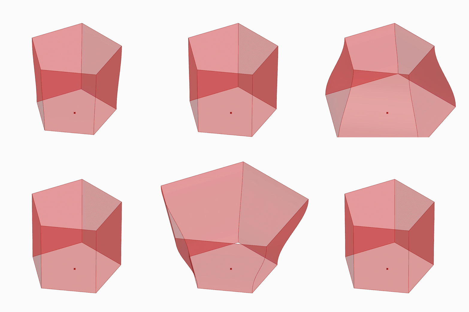
Edit the sizes of base polygons.
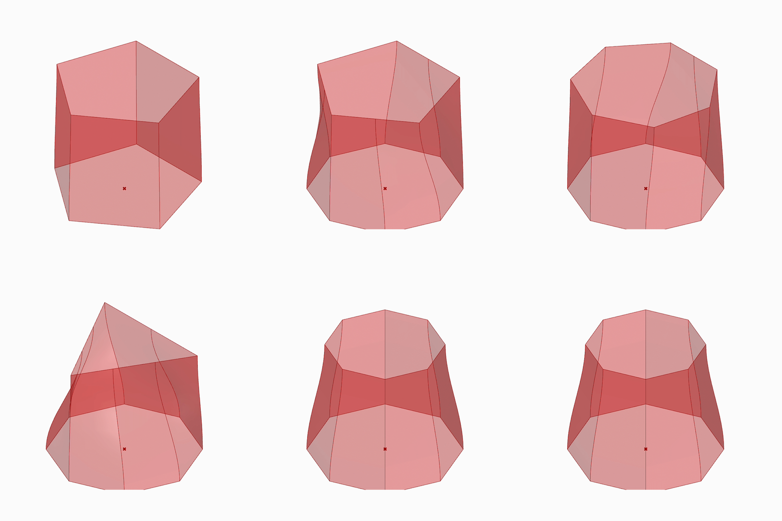
Edit the shape of base polygons.
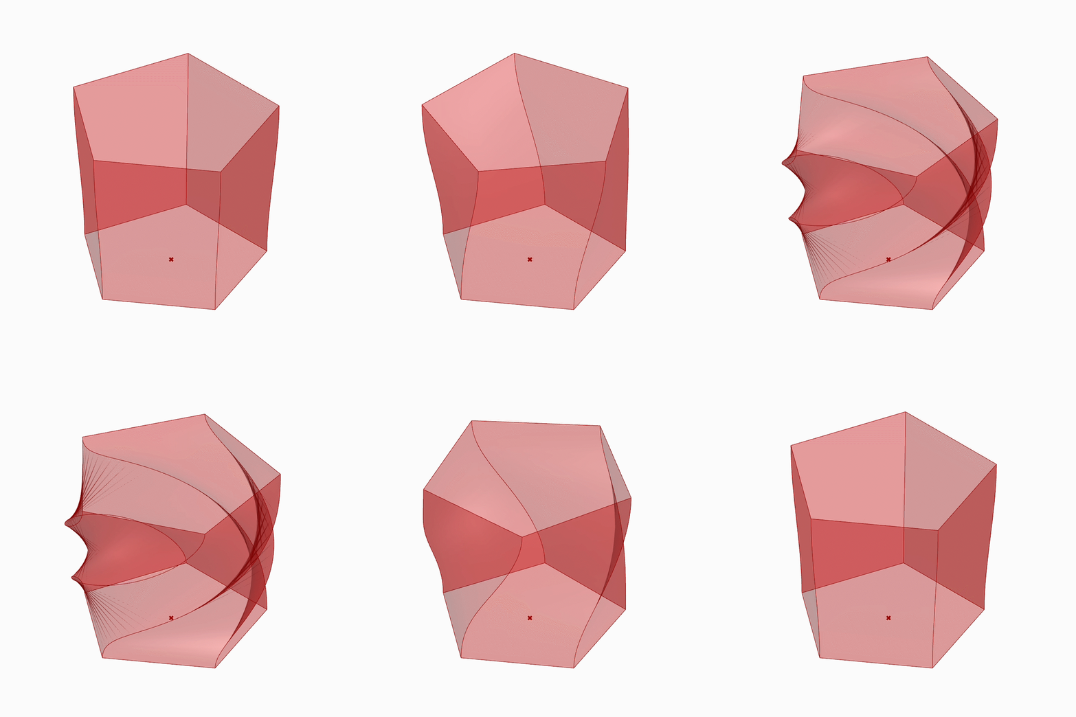
Twist base shape.
02. Digital Toolpath Development
After a geometry has been chosen, a continuous toolpath needs to be developed. The flow of concrete is continuous, and so the toolpath should move up the World Z axis as it moves from layer to layer.


Example of full digital grasshopper workflow. From creating geometry to developing it's toolpath.
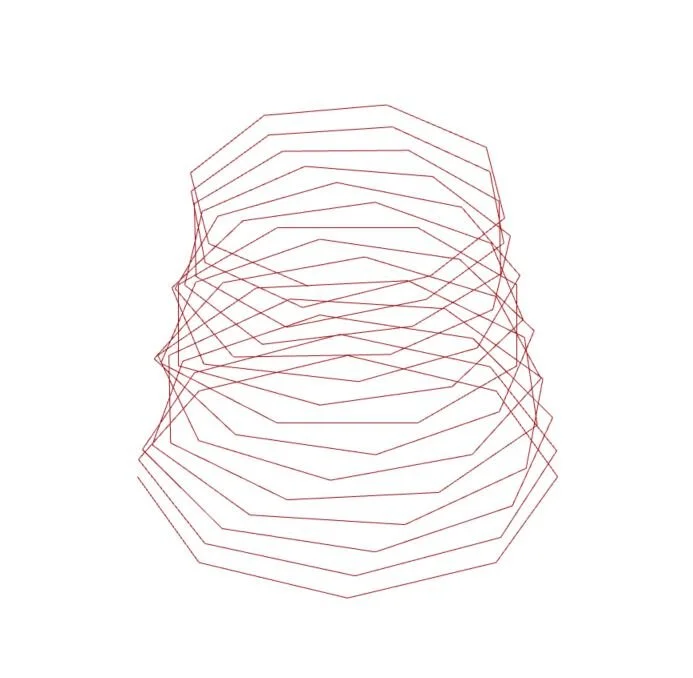
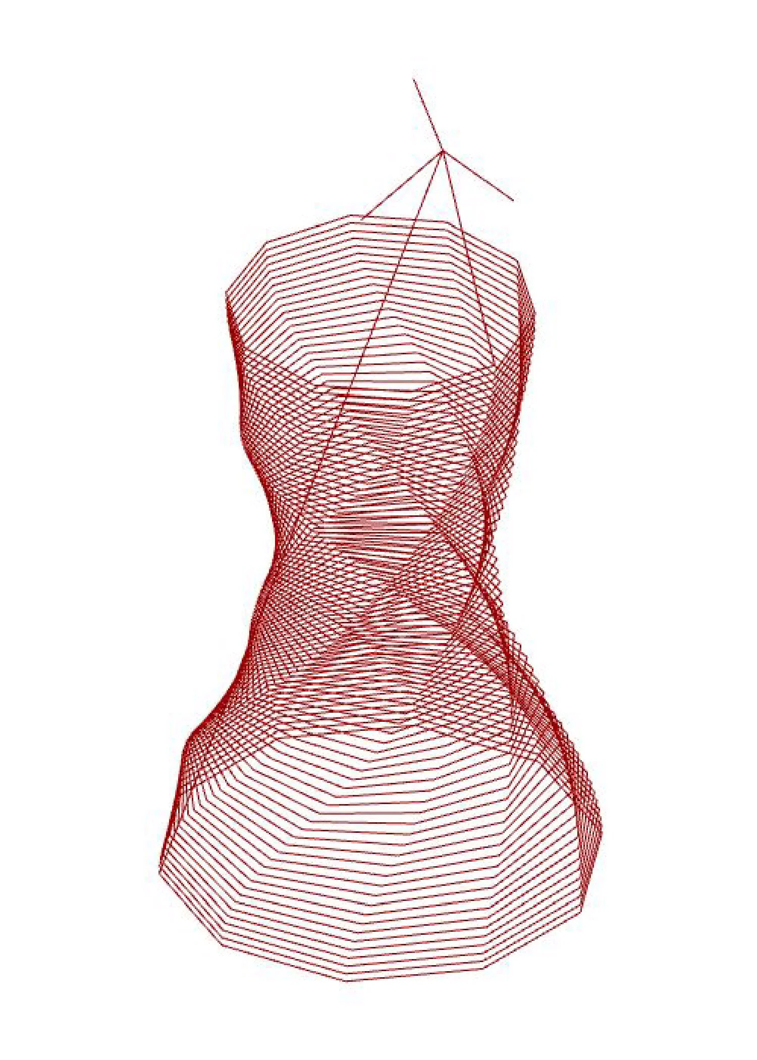
Example of a final geometry toolpath.
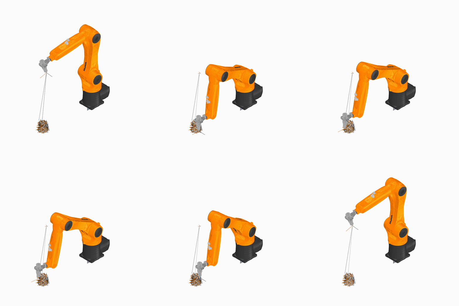
Example of toolpath simulation.
03. Physical Testing
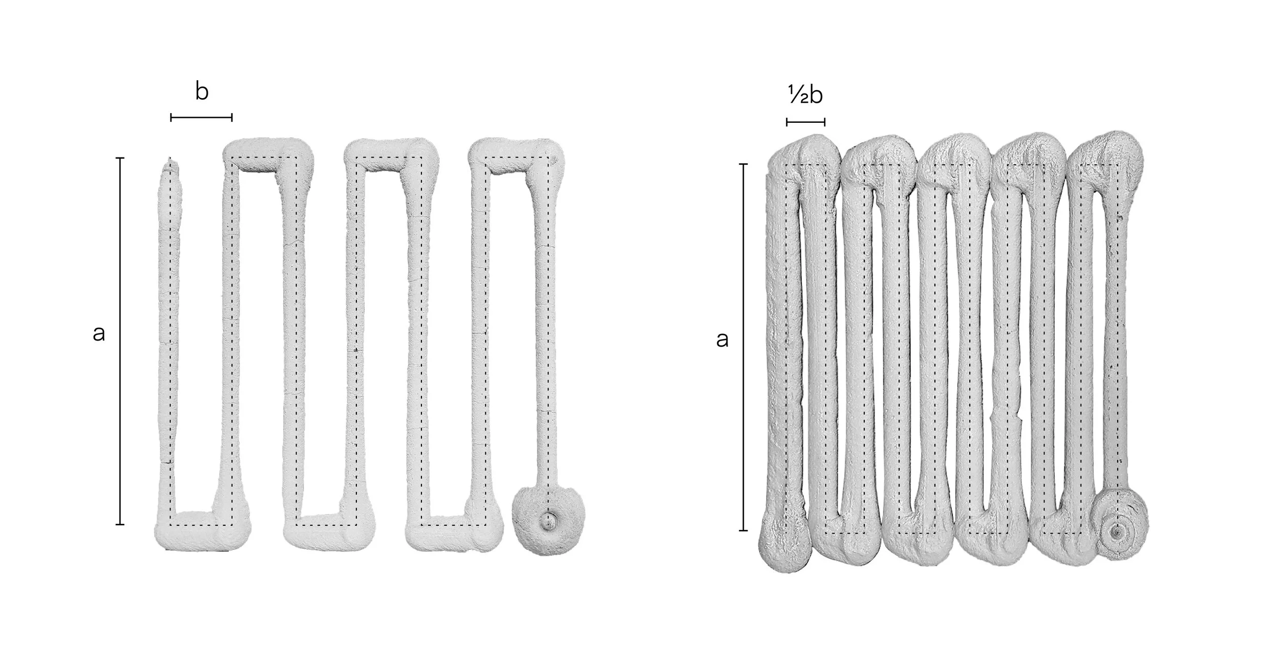
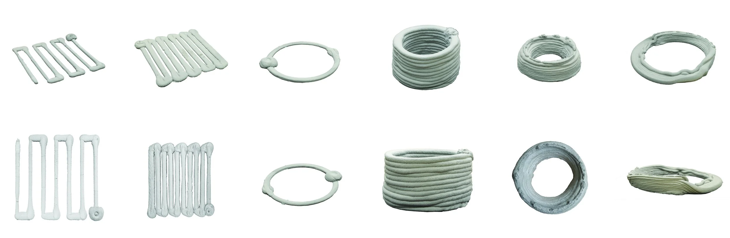
After the digital geometry and toolpaths have been tested in the KUKA simulation, physical testing can occur. Shown are linear and circular tests conducted in the Spring of 2020 - prior to COVID-19 shutdowns.
Physical testing also takes into account: the concrete mix design, the speed the concrete is being pumped out of the nozzle, and the speed the robot is following it’s toolpath.
These tests allowed us to determine speeds that the toolpath should be run at, and that the concrete should be pumped out of the nozzle.
04. Future Goals
The development of an efficient, and well-researched method for concrete 3D printing allows for the development of intricate geometries and forms. Below is an example of a possible column that could be created using the method developed in research. A series of views showing the resulting toolpath are followed by a sped up simulation of the robot running the print.
Iso
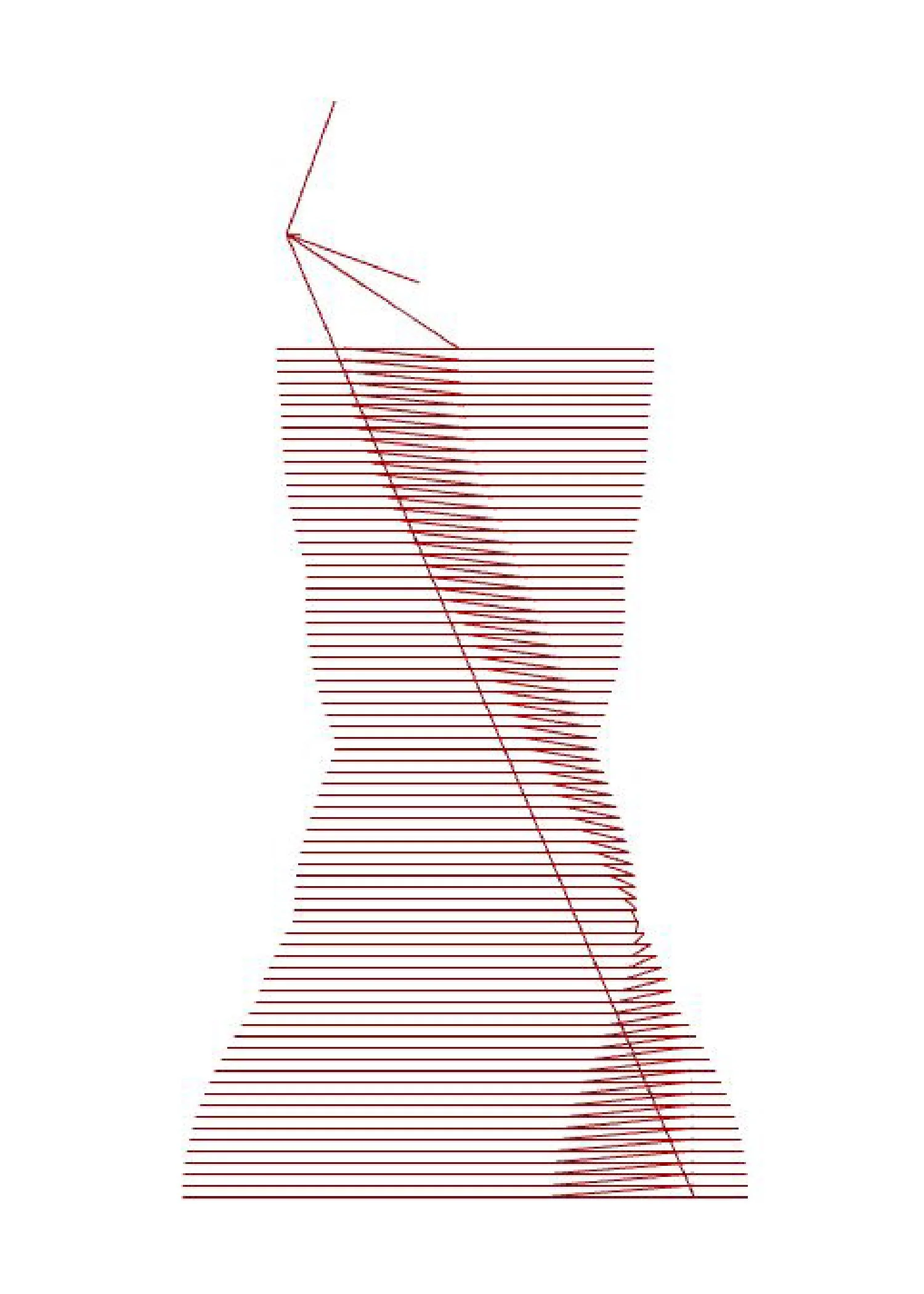
Front
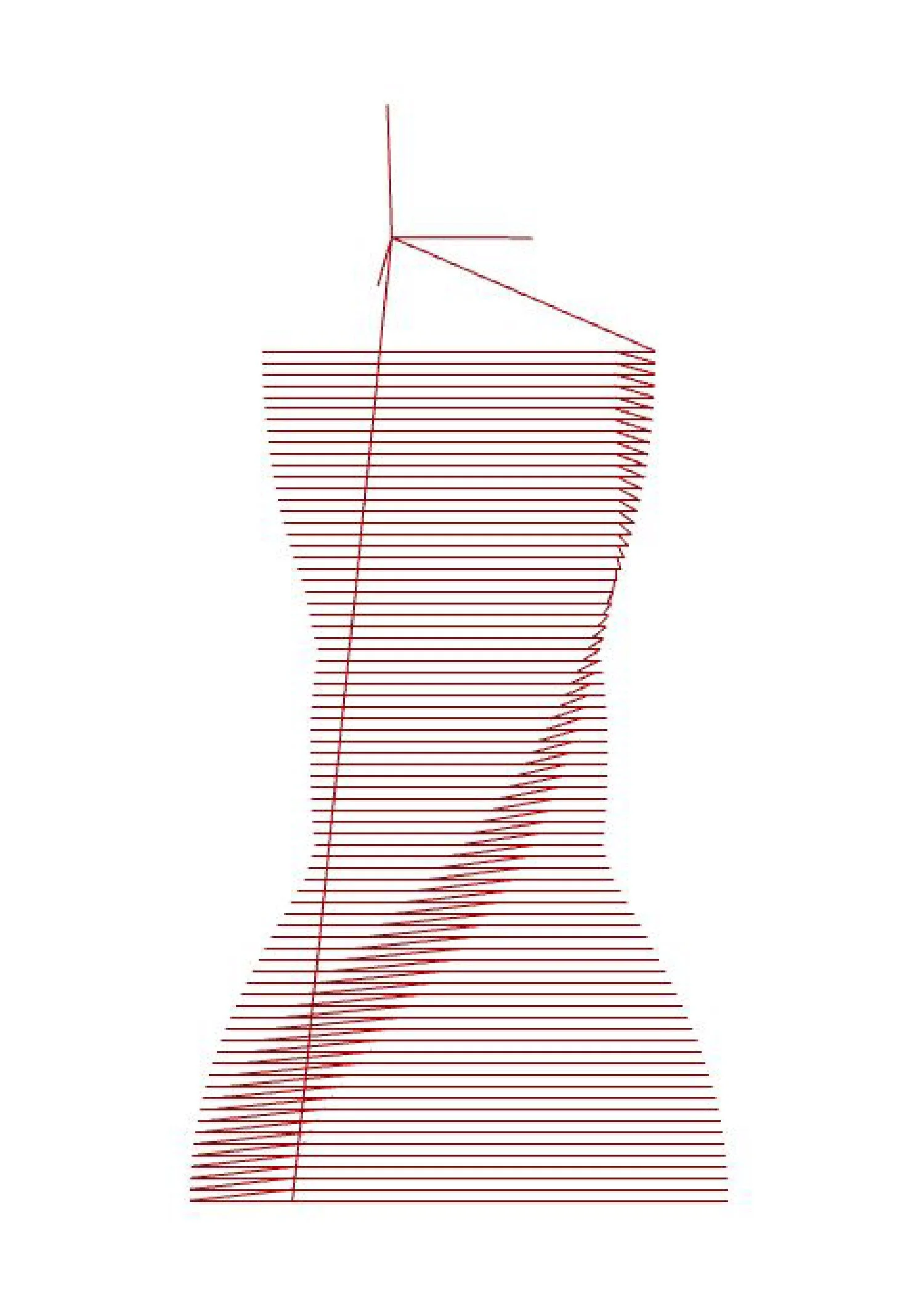
Right
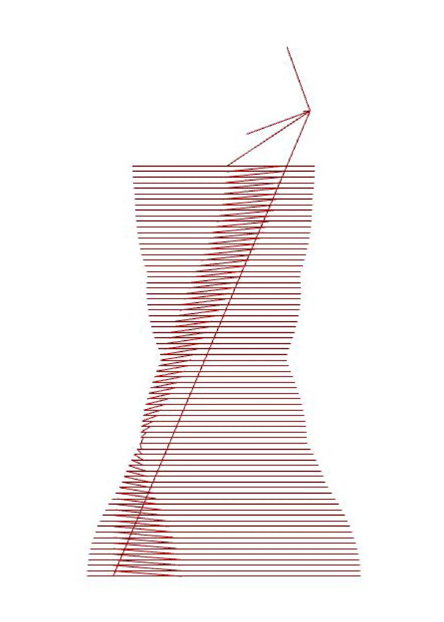
Back
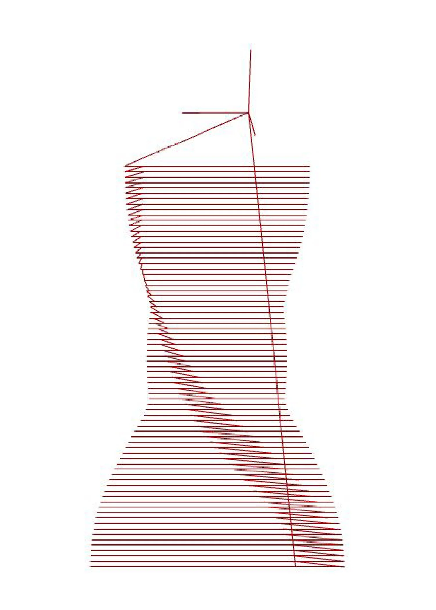
Left
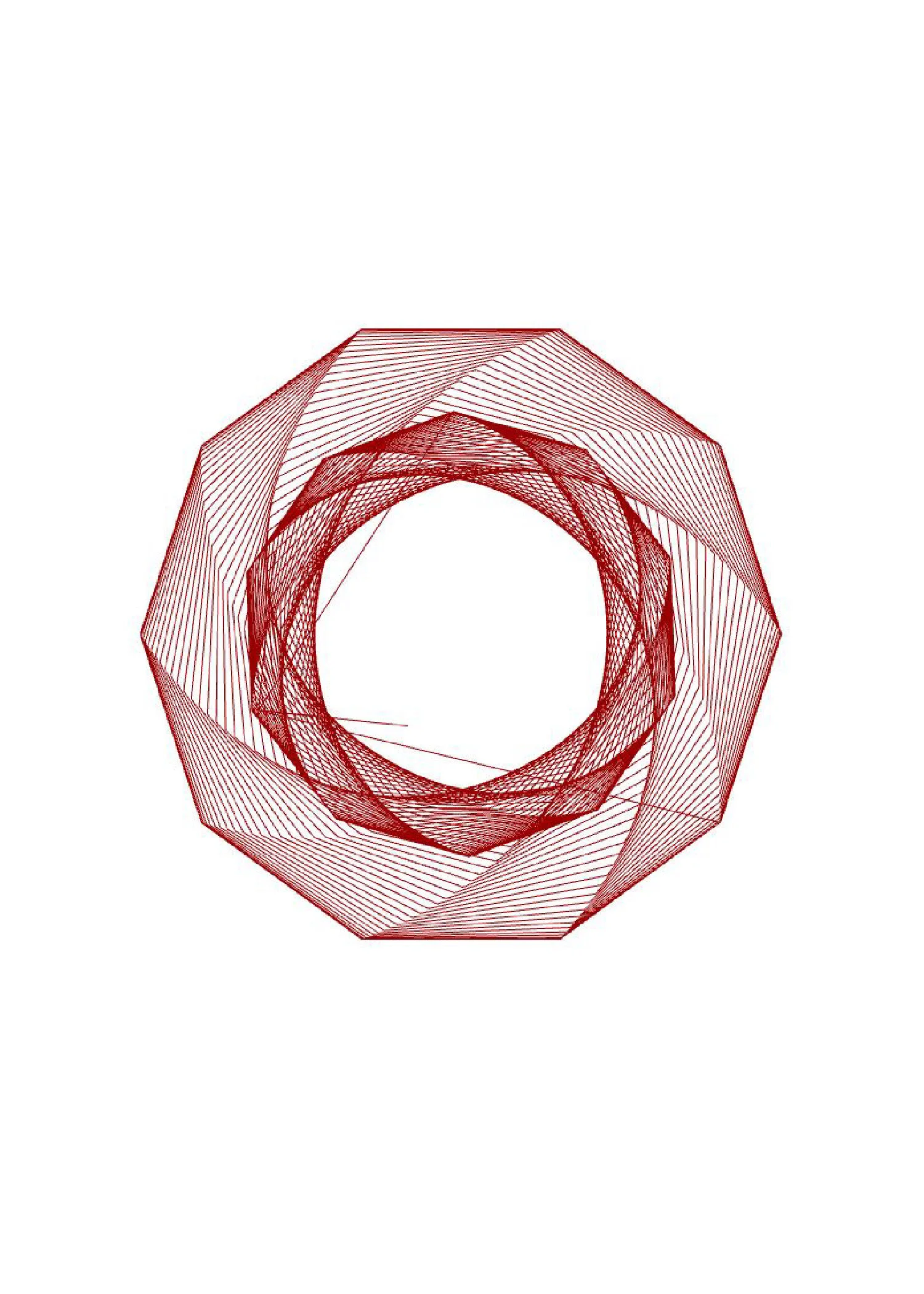
Top
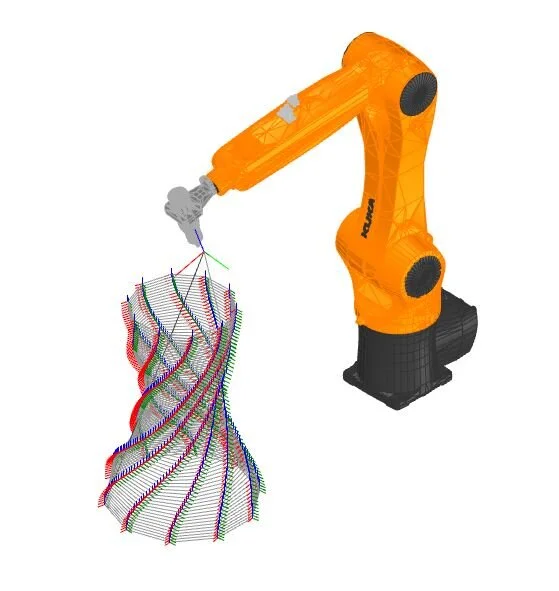
Example of Final Toolpath Simulation with KUKA robot.